This page provides information on the VRayTexFalloff node.
Overview
VRayTexFalloff produces a gradient texture based on the angular falloff of the the surface of the geometry to which the texture is applied. The resulting map can simulate the falloff of opacity, reflection, and refraction for surfaces where these properties vary depending on the surface's angle to the camera, such as curved glass or water.
To create the texture, VRayTexFalloff starts with two colors, usually black and white. Placement of these colors on the surface is based on the Falloff Type and Falloff Direction selected. The remainder of the map is generated as a gradient between these two colors, with a gradual falloff between the colors.
For the example shown on the right, VRayTexFalloff is used in the Diffuse channel of a VRayMtl. The Falloff type is set to Perpendicular/Parallel with the Falloff Direction set to world Y Axis. Solid colors of bright orange and dark green are used for the Front Color and Side Color parameters.

UI Path: ||Toolbar|| > V-Ray Menu icon > Textures > VRayTexFalloff

Attribute Settings
Base Parameters

Front / Side Color – Sets the extreme ends of the range of colors for the Falloff Map's gradient. The specific placement of these colors on the surface is determined by Falloff Type and Falloff Direction.
Falloff Type – Specifies the type of falloff:
Towards/away – Based on face normal directions. Faces with normals that point in the Falloff Direction generate the Front Color while those facing in the opposite direction (180 degrees off the falloff direction) generate the Side Color.
Perpendicular/Parallel – Based on face normal directions. Faces with normals that point in the Falloff Direction generate the Front Color while those facing in a perpendicular direction (90 degrees off the falloff direction) generate the Side Color.
Fresnel – Based on changes to the index of refraction (IOR) over the surface due to Fresnel calculations. Faces with normals that point in the Falloff Direction generate the Front Color and those facing in other directions generate varying colors depending on the IOR set by Fresnel Index Of Reflection.
Distance blend – Sets the falloff range based on distance from the camera, as specified by Near Distance and Far Distance. This option is useful for generating a Z-depth type of map when rendering a very large object such as terrain, where the Falloff Map can be used as a mask to dim distant details. For more information, see the Distance Falloff Type example below.
Falloff Direction – Specifies the falloff direction to be used by the Falloff Type.
Viewing Direction (Camera Z-Axis) – Uses the camera viewing direction. This is the most common selection.
viewX / viewY –Uses one of the camera's other axes.
Explicit direction –Uses the direction specified by the Explicit direction parameter.
local X / local Y / local Z –Uses one of the object's local axes.
worldX / world Y / world Z –Uses one of the world axes.
Mode Specific Parameters

Explicit direction – Specifies the direction for falloff when Falloff Direction is set to Explicit direction.
Fresnel index Of reflection – Defines the IOR (Index of Refraction)when Falloff Type is set to Fresnel.
Near distance – When Falloff Type is set to Distance, parts of the surface at this distance from the camera will receive the Front Color. For more information, see the Distance Falloff Type example below.
Far distance – When Falloff Type is set to Distance, parts of the surface at this distance from the camera will receive the Side Color. For more information, see the Distance Falloff Type example below.
Extrapolate – When enabled, the effect continues beyond the range set by Near Distance and Far Distance. Parts of the surface nearer than Near Distance receive the Front Color, while parts farther from the camera than Far Distance will receive the Side Color.
Remap Curves

Enable color map – Turns on the Remap Curves.
mix – Controls the mix of the Front color and the Side color.
red – The intensity of the red channel.
green – The intensity of thegreen channel.
blue – The intensity of the blue channel.
reset – Resets all curves to default values.
Diagram and Gradient controls
The following controls can be used in the color gradients and diagrams:
Double click – Creates a new point or changes an existing one.
Left button drag – Moves the selected point(s).
Left button drag over the left or bottom rulers (diagrams only) – Scale the diagram in the corresponding direction.
Middle button drag over the background – Drags the visible area. If the Ctrl key is pressed, the background can be dragged instead, thus transforming the diagram.
Mouse wheel – Zoom in/out. If the Ctrl key is pressed, the zoom will occur on the background instead, thus transform the diagram.
Right click – Brings out a drop-down menu where points can be added, edited, or deleted, fit the entire diagram or gradient into the view, clear the diagram, and load and save the diagram it to a file.
Output Parameters
These parameters can adjust the transition between Front Color and Side Color over the Falloff Map's gradient.

Invert – Inverts the color values.
Clamp – Clamps the color values.
Alpha from RGB intensity – Takes the alpha information from the intensity of the RGB.
Output amount – Determines the alpha multiplier.
RGB offset – Allows a color offset to the produced RGB values.
RGB level – Determines the intensity of the falloff effect.
Bump amount – Defines how much bump is produced.
Example: Distance Falloff Type
In the example below, the Falloff type has been set to Distance blend and mapped to the diffuse color of the V-Ray Material on the humbucker pickups on the guitar.

Near distance: 0, Far distance: 27
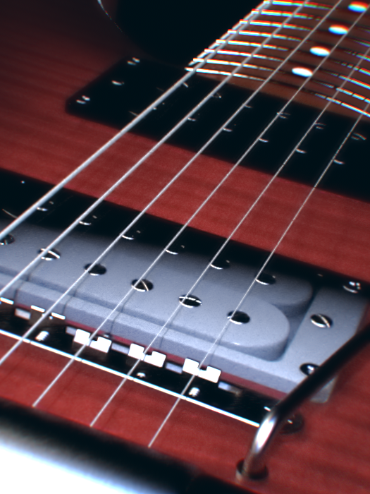

Near distance: 20, Far distance: 27