This page contains information about the V-Ray TexCellular node.
Overview
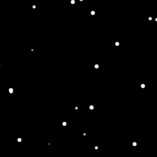
The V-Ray Cellular Texture map generates a procedural cellular noise pattern.

Settings
Type – Specifies which type to use for the Cellular texture. The choices are Dots, Chips, Cells, Chess Cells, or Plasma.
Background Color – Controls the color of the background of the Cellular procedural texture.
Center Color – Controls the color of the center of the cells.
Edge Color – Controls the color of the edges of the cells in the Cellular procedural texture.
Size – Controls the size of the Cellular procedural texture. For more details, please see the Size examples below.
Spread – Controls the spread of the procedural Cellular texture. For more details, please see the Spread examples below.
Density – Controls the Density of the Cellular texture. For more details, please see the Density examples below.
Low – Controls the low threshold (background color). For more details, please see the Low examples below.
Middle – Controls the middle threshold (edge color). For more details, please see the Middle examples below.
High – Controls the high threshold (center color). For more details, please see the High examples below.
Fractal – Enables the addition of fractal generation. Only available with Dots and Chips Types.
Fractal Iterations – Controls the number of fractal iterations. For more details, please see the Fractal Iterations examples below.
Fractal Roughness – Controls the roughness of the fractal. A value of 0.0 is very rough and a value of 1.0 is very smooth, which negates the fractal. For more details, please see the Fractal Roughness examples below.

Default Color – Specifies a color when there are no valid uvw coordinates. Mult – Specifies a multiplier for the texture color. Offset – Color corrects the texture by adding the RGB color values specified here to the RGB color values in the texture. Invert – When enabled, the resulting texture color is inverted. Source – Specifies the alpha source from Alpha, Color, and Opaque. Use – Differentiates between textures exported from different applications. You can choose between Color Intensity (3ds Max) and Color Luminance (Maya). Mult – Specifies a multiplier for the texture alpha. Offset – Specifies an additional offset for the texture alpha. Invert – When enabled, the resulting texture alpha is inverted, too. If disabled, just the color is inverted. Placement Type – Specifies the way the valid portion of the texture is applied. The options are Full, Crop, and Place. U/V – Specifies the U/V coordinates of the valid texture sector. W – Specifies the width of the valid texture sector. H – Specifies the height of the valid texture sector. Jitter – Specifies the amount of random placement variation. Tile U – When enabled, there is horizontal tiling. Tile V – When enabled, there is vertical tiling. Enabled – Enables the UV noise. Amount – Specifies the UV noise amount. Levels – Specifies the UV noise iterations. Size – Specifies the UV noise size. Animated – When enabled, the noise is animated. Phase – Specifies the UV noise phase.Color Tweaks

Alpha Tweaks

Placement

UV Noise

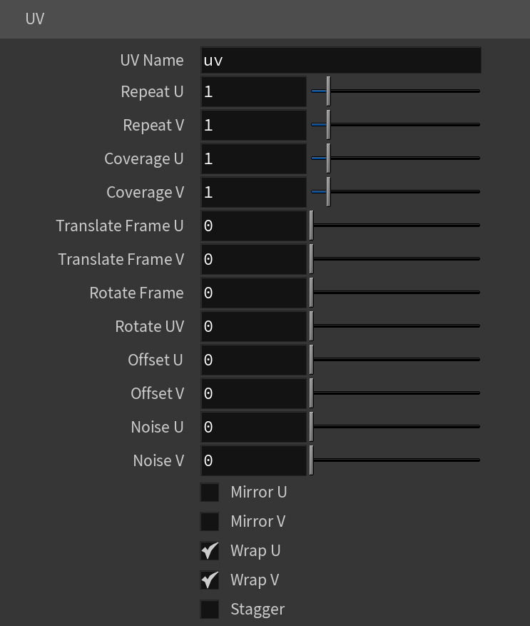
Type – Specifies the mapping type. UV Name – The name of the UV channel that is used. Repeat U – Multiplier for U values. Repeat V – Multiplier for V values. Coverage U – U values are remapped to 1.0. Coverage V – V values are remapped to 1.0. Translate Frame U – Translates the frame in U direction after applying rotate_frame (and before wrap, coverage, clamp). Translate Frame V – Translates the frame in V direction after applying rotate_frame (and before wrap, coverage, clamp). Rotate Frame – Rotates the frame after applying UV noise. Rotate UV – Rotates the UVs after mirroring. Offset U – Offset added to U before mirroring (after wrap, coverage, clamp). Offset V – Offset added to V before mirroring (after wrap, coverage, clamp). Noise U – Noise magnitude multiplier in U direction. Nose V – Noise magnitude multiplier in V direction. Mirror U – When enabled, every other tile outside the [0;1] range is mirrored in U. Mirror V – When enabled, every other tile outside the [0;1] range is mirrored in V. Wrap U – When enabled, U values outside the [0;1] range wrap back to [0;1]. Wrap V – When enabled, V values outside the [0;1] range wrap back to [0;1]. Stagger – When enabled, tiles in the V direction add +0.5 to the U value for a 'staggering' effect. Type – Specifies the type of projection mapping to use from the following:None Planar Projection Camera – Selects a camera. Projection Camera (LOP) – Same as Projection Camera parameter but for use in the LOP context. Fit Fill – Specifies how the projection is fitted. Vertical – Fitted vertically. Fit Type – Specifies the type of fitting to use: None U / V Angle – Specifies the U / V mapping angle. Film Gate W / H – Specifies the width / height of the film gate. Hide Backface – Determines whether to project on back faces of polygons. Hide Occluded – Determines whether to project on occluded points when using the Perspective Type. Object Space – When enabled, the projection is applied in the object space of the currently shaded geometry. Use Reference Points – Uses reference mesh/rest inputs for projection calculations. Mapping Type – Specifies the type and shape of the texture from the following: Spherical, Angular, Cubic, Mirror Ball, Screen, Spherical (3ds Max), Cylindrical (3ds Max), Shrink Wrap (3ds Max), and Spherical (V-Ray). Horizontal Flip – Flips the environment horizontally. Vertical Flip – Flips the environment vertically. Horizontal Rotation – Specifies the horizontal rotation (left and right). Vertical Rotation – Specifies the vertical rotation (up and down). Texture Rotation – Specifies the texture rotation. Wrap U – If true, U values outside the [0;1] range wrap back to [0;1]. You can choose between the No Wrapping, Wrap and Mirror Tile options. Wrap V – If true, V values outside the [0;1] range wrap back to [0;1]. You can choose between the No Wrapping, Wrap and Mirror Tile options. Wrap X – If true, X values outside the [0;1] range wrap back to [0;1]. You can choose between the No Wrapping, Wrap and Mirror Tile options. Crop U / V / W – Enables or disables cropping in the U / V / W direction. DUVW Scale – Specifies an additional scale factor for the texture derivatives. Ground – Enables ground projection of the texture. Ground Radius – When Ground is enabled, this specifies the radius of the ground. Ground Position – When Ground is enabled, this specifies the coordinates for the ground.Mapping

Spherical
Cylindrical
Ball
Cubic
Tri-Planar
Perspective
Fit Fill – Fitted to fill the space.
Horizontal – Fitted horizontally.
Match Camera Film Gate
Match Camera Resolution

Example: Size

Dots Size: 0.05

Dots Size: 0.1

Dots Size: 0.2

Chips Size: 0.2

Chips Size: 0.35

Chips Size: 0.5

Cells Size: 0.1

Cells Size: 0.2

Cells Size: 0.5

Chess Cells Size: 0.1

Chess Cells Size: 0.2

Chess Cells Size: 0.5

Plasma Size: 0.05

Plasma Size: 0.07

Plasma Size: 0.2
Move the slider to see the example renders.
Example: Spread
Dots Spread: 0.5

Dots Spread: 1.0

Dots Spread: 1.5
Chips Spread: 0.5

Chips Spread: 1.0

Chips Spread: 2.0

Cells Spread: 0.1
Cells Spread: 0.5

Cells Spread: 1.0

Chess Cells Spread: 0.1
Chess Cells Spread: 0.5

Chess Cells Spread: 0.9
Plasma Spread: 1.0

Plasma Spread: 3.0

Plasma Spread: 5.0
Move the slider to see the example renders.
Example: Density
Dots Density: 0.1
Dots Density: 0.25

Dots Density: 1.0
Chips Density: 0.25

Chips Density: 0.7

Chips Density: 1.5

Cells Density: 0.15
Cells Density: 0.25

Cells Density: 0.5

Chess Cells Density: 0.15
Chess Cells Density: 0.25

Chess Cells Density: 0.5

Plasma Density: 0.5

Plasma Density: 1.0

Plasma Density: 2.0
Move the slider to see the example renders.
Example: Low
The Dots examples below use Size: 0.25, Spread: 0.5, and Density: 1.5. The Edge Color is blue for visual clarity.

Dots Low: 0.0

Dots Low: 0.5

Dots Low: 1.0
Move the slider to see the example renders.
The Chips examples below use Size: 1.0, Spread: 0.75, and Density: 3.0. The Edge Color is blue for visual clarity.

Chips Low: 0.0

Chips Low: 0.5

Chips Low: 0.9
Move the slider to see the example renders.
Example: Middle
The Dots examples below use Size: 0.25, Spread: 0.5, and Density: 1.5. The Edge Color is blue for visual clarity.

Dots Middle: 0.0

Dots Middle: 0.5

Dots Middle: 1.0
Move the slider to see the example renders.
The Chips examples below use Size: 1.0, Spread: 0.75, and Density: 3.0. The Edge Color is blue for visual clarity.

Chips Middle: 0.0

Chips Middle: 0.5

Chips Middle: 1.0
Move the slider to see the example renders.
Example: High

Dots High: 0.0

Dots High: 0.75

Dots High: 1.0
Move the slider to see the example renders.
The Chips examples below use Size: 1.0, Spread: 0.75, and Density: 3.0. The Edge Color is blue for visual clarity.

Chips High: 0.0

Chips High: 0.75

Chips High: 1.0
Move the slider to see the example renders.
Example: Fractal Iterations

Fractal not enabled

Fractal Iterations: 1.75

Fractal Iterations: 3.0
Move the slider to see the example renders.

Fractal not enabled

Fractal Iterations: 1.75

Fractal Iterations: 3.0
Move the slider to see the example renders.
Example: Fractal Roughness
Fractal Roughness: 0.0

Fractal Roughness: 0.5

Fractal Roughness: 0.9
Move the slider to see the example renders.
The Chips examples below use Size: 1.0, Spread: 0.75, Density: 3.0, and Fractal Iterations: 3.0.
Fractal Roughness: 0.0

Fractal Roughness: 0.5

Fractal Roughness: 0.9
Move the slider to see the example renders.